


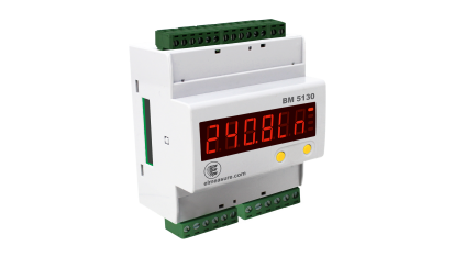
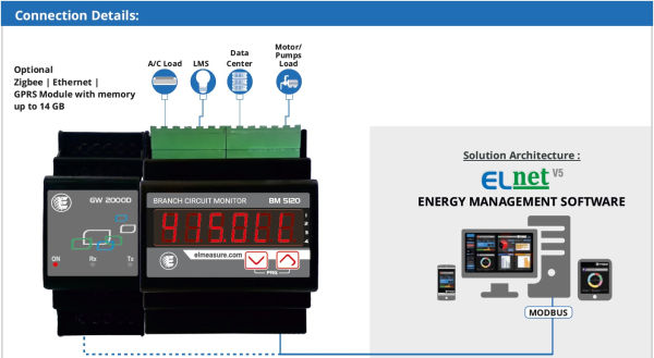
The Branch Circuit Monitor (BM) is very ideal for Data Centres. It can connect and control up to 12 channels for Branch Monitoring. Controlling can be done using add on relay unit and RS485. It can measure voltage, current, power, and energy of every circuit connected in a power distribution unit or rack. Split core or regular CTs can be used to monitor currents of each circuit.
Features:
Measures:
Specifications of Zigbee (Coordinator & Router):
|
Network support |
IEEE802.15.4 & Zigbee |
|
Data Rating |
256 kbps |
|
Frequency Band |
864-865 MHz (16 channels) with auto scanning |
|
Modulation Technique |
DSSS |
|
Wireless Security |
AES 128-bit encryption |
|
Tx O/P Power |
4.5dBm Rx |
|
Sensitivity |
-97dBm |
|
Distance Covered |
20 metres |
Technical Specifications:
|
Accuracy |
Class 1.0 (default), Class 0.5 (optional on request) |
|
Measurement Range |
1:500 for channels 1 & 2, 1:120 for channels 3 & 4 |
|
Sensing/measurement |
True RMS, 1 sec. update time, 4 quadrant power & energy |
|
Input Voltage |
4 voltage I/Ps (VR, VY, VB, VN) programmable 110 or 415VLL Nominal (range 80-500VLL) primary programmable up to 999kV. Burden: 0.2VA max. per phase |
|
Input Frequency |
45-65Hz |
|
Input Current |
3 I/P currents (AR, AY, AB) 4 channels-each channel is independently configurable, primary programmable up to 99kA. CT O/P: can be up to 1000mV or 100mA from split core CTs or hanging CTs |
|
Aux. Supply |
Control power: 180-300V AC/DC 40-70Hz Burden: 5VA max. |
|
CT/PR ratio max. |
2000MVA programmable |
|
Communication |
RS485interface, industry standard MODBUS RTU protocol Baud rate: 4800 to 19200bps (preferred 9600bps) Isolation: 2000V AC isolation for 1 minute between communication and other circuits |
Safety & Environment Specifications:
Safety:
Environment:
|
Operating Temperature |
-100C to +550C (140F to 1310F) |
|
Storage Temperature |
-250C to +700C (-130F to 1580F) |
|
Humidity |
5 to 95% (non-condensing) |
|
Recommended connecting wire |
12 to 14 SWG (10 to 12 AWG) |
*****ECO-FRIENDLY*****
Applications:
Benefits:
Note: additional error of 0.1% of full scale for meter I/P current below 500mA for 5A setting.
Communication Register Map:
|
Sr. No. |
Parameter |
Data Type |
Address |
|||
|
Channel-1 |
Channel-2 |
Channel-3 |
Channel-4 |
|||
|
1 |
W Total |
Float |
4101 |
4201 |
4301 |
4401 |
|
2 |
W R Phase |
Float |
4103 |
4203 |
4303 |
4403 |
|
3 |
W Y Phase |
Float |
4105 |
4205 |
4305 |
4405 |
|
4 |
W B Phase |
Float |
4107 |
4207 |
4307 |
4407 |
|
5 |
PF avg. (Inst.) |
Float |
4109 |
4209 |
4309 |
4409 |
|
6 |
PF R Phase |
Float |
4111 |
4211 |
4311 |
4411 |
|
7 |
PF Y Phase |
Float |
4113 |
4213 |
4313 |
4413 |
|
8 |
PF B Phase |
Float |
4115 |
4215 |
4315 |
4415 |
|
9 |
VLL avg. |
Float |
4117 |
4217 |
4317 |
4417 |
|
10 |
V RY Phase |
Float |
4119 |
4219 |
4319 |
4419 |
|
11 |
V YB Phase |
Float |
4121 |
4221 |
4321 |
4421 |
|
12 |
V BR Phase |
Float |
4123 |
4223 |
4323 |
4423 |
|
13 |
VLN avg. |
Float |
4125 |
4225 |
4325 |
4425 |
|
14 |
V R Phase |
Float |
4127 |
4227 |
4327 |
4427 |
|
15 |
V Y Phase |
Float |
4129 |
4229 |
4329 |
4429 |
|
16 |
V B Phase |
Float |
4131 |
4231 |
4331 |
4431 |
|
17 |
A Total |
Float |
4133 |
4233 |
4333 |
4433 |
|
18 |
A R Phase |
Float |
4135 |
4235 |
4335 |
4435 |
|
19 |
A Y Phase |
Float |
4137 |
4237 |
4337 |
4437 |
|
20 |
A B Phase |
Float |
4139 |
4239 |
4339 |
4439 |
|
21 |
Frequency Hz |
Float |
4141 |
4241 |
4341 |
4441 |
|
22 |
Wh Received |
Float |
4143 |
4243 |
4343 |
4443 |
|
23 |
Wh R Phase |
Float |
4145 |
4245 |
4345 |
4445 |
|
24 |
Wh Y Phase |
Float |
4147 |
4247 |
4347 |
4447 |
|
25 |
Wh B Phase |
Float |
4149 |
4249 |
4349 |
4449 |
|
26* |
L.H. Received |
Unsigned Long |
4151 |
4251 |
4351 |
4451 |
|
27* |
L.H. R Phase |
Unsigned Long |
4153 |
4253 |
4353 |
4453 |
|
28* |
L.H. Y Phase |
Unsigned Long |
4155 |
4255 |
4355 |
4455 |
|
29* |
L.H. B Phase |
Unsigned Long |
4157 |
4257 |
4357 |
4457 |
|
30* |
VAR Total |
Float |
4159 |
4259 |
4359 |
4459 |
|
31* |
VAR R Phase |
Float |
4161 |
4261 |
4361 |
4461 |
|
32* |
VAR Y Phase |
Float |
4163 |
4263 |
4363 |
4463 |
|
33* |
VAR B Phase |
Float |
4165 |
4265 |
4365 |
4465 |
|
34* |
VA Total |
Float |
4167 |
4267 |
4367 |
4467 |
|
35* |
VA R Phase |
Float |
4169 |
4269 |
4369 |
4469 |
|
36* |
VA Y Phase |
Float |
4171 |
4271 |
4371 |
4471 |
|
37* |
VA B Total |
Float |
4173 |
4273 |
4373 |
4473 |
|
38* |
VAh Total |
Float |
4175 |
4275 |
4375 |
4475 |
|
39* |
VARh IND Total |
Float |
4177 |
4277 |
4377 |
4477 |
|
40* |
VARh CAP Total |
Float |
4179 |
4279 |
4379 |
4479 |
|
41* |
VAh R Phase |
Float |
4181 |
4281 |
4381 |
4481 |
|
42* |
VARh Y Phase |
Float |
4183 |
4283 |
4383 |
4483 |
|
43* |
VARh B Phase |
Float |
4185 |
4285 |
4385 |
4485 |
|
44* |
VARh IND R Phase |
Float |
4187 |
4287 |
4387 |
4487 |
|
45* |
VARh IND Y Phase |
Float |
4189 |
4289 |
4389 |
4489 |
|
46* |
VARh IND B Phase |
Float |
4191 |
4291 |
4391 |
4491 |
|
47* |
VARh CAP R Phase |
Float |
4193 |
4293 |
4393 |
4493 |
|
48* |
VARh CAP Y Phase |
Float |
4195 |
4295 |
4395 |
4495 |
|
49* |
VARh CAP B Phase |
Float |
4197 |
4297 |
4397 |
4497 |
*=Optional

 Facebook
  Twitter
  Linkedin